


Blog
Primare Connection Methods
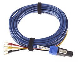
Standard recommended practice is to connect the red subwoofer cable lead to the positive speaker terminal of one channel, the yellow lead to the positive speaker terminal of the other channel, and the black lead being connected to whichever of the “-“ outputs is most convenient or, alternatively, a chassis screw to connect to “-“ or ground.
Note: our recommendation is to always connect the black wire to the ground collar of an RCA plug or the ground post of an XLR and connect to any unused input on the amp or preamp, rather than using chassis ground.
However, certain amplifiers’ output topologies, including some from Primare, prevent the use of this connection scheme due to their need to most effectively use the power supply of the amplifier which results in reversal of phase, or inverted phase, output in one of the channels of the partnering amp to which the sub is being connected. This can result in the standard connection scheme not providing the correct signal to the subwoofer’s, or in worst-case scenarios may cause damage to the sub or amplifier.
In the case of Primare multi-channel amps a variation of the standard connection scheme can be used as long as careful selection of specific output channels is observed.
Below are listed the recommended connection schemes for Primare amplifiers.
A60/A32 stereo amplifiers
One sub-bass system in stereo configuration:
- Red to one positive speaker terminal
- Yellow to the other positive speaker terminal
- Black to ground on RCA collar or XLR pin into any unused amp or preamp input
I22/I32/A34.2 stereo amplifiers
One sub-bass system in stereo configuration: whether wireless or direct connection, it is recommended to use low-level pre-amp output connection.
Note: high-level connection with one sub is possible, but only with one channel connected, due to the reversed/inverted phase output on the left channel. For this, we recommend connecting the red and yellow cables to the Right red (+) speaker output and the black wire to RCA collar or XLR ground pin to unused input on amp or preamp
Two sub-bass systems:
- Right channel connection:
- Red and yellow cables connected to Red (+) speaker output
- Black to RCA collar or XLR ground pin to unused input on amp or preamp
- Left channel connection:
- Red and yellow cables connected to Black (-) speaker output
- Black to RCA collar or XLR ground pin to unused input on amp or preamp
- Note: combined Yellow and Red wire bundle may provide too much single input. If this is the case, simply disconnect one of the cables, red or yellow, and cut off the bare wire (or cover with electrical tape) on the unused cable.
A34.2 Bridged
When using a pair of A34.2 amplifiers bridged to mono:
One sub-bass system:
- Red to the positive speaker terminal of one amplifier
- Yellow to the positive speaker terminal of the other amplifier
- Black to ground on RCA collar or XLR pin into any unused amp or preamp input
Two sub-bass systems:
- Right channel connection:
- Red and yellow cables connected to Red (+) speaker output
- Black to RCA collar or XLR ground pin to unused input on amp or preamp
- Left channel connection:
- Red and yellow cables connected to Red (+) speaker output
- Black to RCA collar or XLR ground pin to unused input on amp or preamp
- Note: combined Yellow and Red wire bundle may provide too much single input. If this is the case, simply disconnect one of the cables, red or yellow, and cut off the bare wire (or cover with electrical tape) on the unused cable.
SPA23 five-channel integrated amplifier
Main front left and right channels – the red speaker output is active and the black speaker output is ground, so the follow this connection scheme:
- Red cable to right Red positive speaker terminal
- Yellow cable to left Red positive speaker terminal
- Black cable to ground on RCA collar or XLR pin into any unused amp or preamp input
Surround left and right channels – the black speaker output is active and red speaker output is ground, so follow this connection scheme:
- Red cable to right Black negative speaker terminal
- Yellow cable to left Black negative speaker terminal
- Black cable to ground RCA collar or XLR ground pin to any unused amp or preamp input
Center channel – the black speaker output is active and red speaker output is ground, so follow this connection scheme:
- Red and yellow cables connected to Black (-) speaker output
Note: combined Yellow and Red wire bundle may provide too much single input. If this is the case, simply disconnect one of the cables, red or yellow, and cut off the bare wire (or cover with electrical tape) on the unused cable.
- Black to RCA collar or XLR ground pin to unused input on amp or preamp
A30.7 multi-channel amplifier
Note: channels 1,2,3,4 are in phase, and opposite to 5,6,7.
- 1,2,3,4 – the black speaker output is active and the red speaker output is ground:
- Red cable to right Black [active] speaker output
- Yellow cable to left/Black [active] speaker output
- Black cable to right or left Red [ground] speaker output [or RCA collar/XLR ground pin to unused input on amp or preamp]
- 5, 6, 7 red speaker output is active and black speaker output is ground:
- Red cable to right/Red [active] speaker output
- Yellow cable to left/Red [active] speaker output
- Black cable to right or left to Black [ground] speaker output [or RCA collar/XLR ground pin to unused input on amp or preamp]
This results in the following system connection recommendations:
- 5, 6, or 7-channel system
- Channels 5 and 6 main left and right – standard hookup scheme.
- Channel 7 center – standard hookup scheme for single sub per channel.
- Channels 1,2, 3, 4 rear channels in either a 5, 6, or 7.1 system configuration with connection as described below:
- Red cable to right Black [active] speaker output
- Yellow cable to left/Black [active] speaker output
- Black cable to right or left Red [ground] speaker output [or RCA collar/XLR ground pin to unused input on amp or preamp]
- Bi-amp main left and right 5-channel system.
- Channels 1,2, 3, 4 front left and right channels with pairs of outputs connected to bass and treble to respective inputs of the partnering speakers according to the following scheme:
- Red cable to right Black [active] speaker output
- Yellow cable to left/Black [active] speaker output
- Black cable to right or left Red [ground] speaker output [or RCA collar/XLR ground pin to unused input on amp or preamp]
- Channels 5 and 7 rear channels – standard hookup scheme.
- Channel 6 center channel – standard hookup scheme for single sub per channel.
- Channels 1,2, 3, 4 front left and right channels with pairs of outputs connected to bass and treble to respective inputs of the partnering speakers according to the following scheme: